
 HERMESS
Test Cases#
The systems that ship with the package live in
hermess/systems.
Each one is a folder holding a sim_param.txt (network, devices, initialization)
and a sim_dist.txt (disturbances), described in System files.
The list is available at runtime, so it never goes out of date:
import hermess

hermess.list_systems()
dae = hermess.simulate("ieee39", T_end=10.0)
Small systems#
3bus#
Three buses and three lines: a Sauer-Pai synchronous machine at bus 1, a grid-forming converter at bus 3 and a ZIP load at bus 2. The smallest system that still contains both a machine and a converter, which makes it the usual starting point and the one used by most of the test suite. Disturbance: a line opening.
3bus_loadstep#
The same three-bus network with a single small load step instead of the line opening: a minimal setpoint-style event that stays in the linear regime while still exciting the grid-forming converter’s power and frequency response.
3bus_genrou#
A three-bus triangle with two round-rotor GENROU machines (buses 1 and 3) and
a constant-impedance load (bus 2), with excitation and turbine dynamics
deliberately excluded (AVRCONST / GOVCONST). This is the cross-tool
validation case for the GENROU machine model, compared against ANDES in CI;
see Validation. Disturbance: a line opening.
3bus_gensal#
The same network with two salient-pole GENSAL machines: the cross-tool validation case for GENSAL (see Validation). Disturbance: a line opening.
3bus_tgov1#
The GENROU pair with a TGOV1 turbine governor closed around each machine and no other speed feedback (D = 0): the cross-tool validation case for TGOV1 (see Validation). Disturbance: a line opening, which leaves a power imbalance for the governors to pick up.
3bus_sexst#
The GENROU pair with the simplified static exciter SEXST closed around each machine: the cross-tool validation case for SEXST (see Validation). Disturbance: a line opening, whose voltage step exercises the exciters.
3bus_avrst1a#
The GENROU pair with the ST1A static exciter (transducer, transient-gain-reduction lead-lag, regulator lag): the cross-tool validation case for AVRST1A (see Validation). Disturbance: a line opening.
3bus_ieeedc1a#
The GENROU pair with the IEEE DC1A rotating exciter (Sauer-Pai parameter set): the cross-tool validation case for IEEEDC1A (see Validation). Disturbance: a line opening.
3bus_avrac1a#
The GENROU pair with the AC1A exciter in its small-signal form, at a high-gain fast-regulator parameter set: the cross-tool validation case for AVRAC1A (see Validation). Disturbance: a line opening.
3bus_psskundur#
The GENROU pair with the SEXST exciter and the Kundur speed-input stabilizer: the cross-tool validation case for PSSKundur (see Validation). Disturbance: a line opening, whose rotor swings exercise the stabilizer path.
3bus_genrou_psse#
The three-bus PSS/E benchmark system (60 Hz): an infinite bus, one
saturation-free GENROU, and a constant-impedance load, transcribed from the
ThreeBusMulti case of the PowerSimulationsDynamics.jl benchmark set. The
cross-tool validation case against a PSS/E-produced trajectory (see
Validation); run it with fn=60 and T_end=20. Disturbance: a
line opening.
3bus_gfm_psid#
Ideal source, droop grid-forming converter (D’Arco parameter set) and constant-impedance load: the cross-tool validation case for GridForming against PowerSimulationsDynamics.jl (see Validation). Disturbance: a load step.
3bus_sauerpai_psid#
Ideal source, the six-state Sauer-Pai machine with constant excitation and mechanical power, and a constant-impedance load: the cross-tool validation case for SynchronousSubtransientSP against PSID (see Validation). Disturbance: a load step.
3bus_shaft5mass_psid#
The Sauer-Pai machine on the five-mass torsional shaft HP-IP-LP-GEN-EXC (Sauer-Pai torsional data): the cross-tool validation case for Shaft5Mass against PSID (see Validation). Disturbance: a load step, whose electrical-torque step rings the torsional modes.
3bus_dynlines_psid#
The Sauer-Pai system with the network itself dynamic (run it with
line_dyn=True): every line current and bus voltage is a differential
state. The cross-tool validation case for the dynamic network against PSID
(see Validation). Disturbance: a load step.
omib_gfm_pscad#
The one-machine-infinite-bus system of the PSCAD Test23 benchmark: the full
D’Arco droop grid-forming converter (active damping, split power-filter
corners) against an ideal source. Validated against both PSID and the PSCAD
electromagnetic trajectory (see Validation). Disturbance: a
reference-power step (the SETPOINT event).
omib_vsm_pscad#
The OMIB of the PSCAD Test08 benchmark: the virtual-synchronous-machine
converter (angle = "VSM" with the Kaura PLL and damped inner control).
Validated against both PSID and PSCAD (see Validation). Disturbance:
a reference-power step.
omib_gfl_pscad#
The OMIB of the PSCAD Test24 benchmark: the current-injecting GridFollowing converter (PI power outers, current-mode inner, reduced-order PLL). Validated against PSID exactly and compared against the PSCAD trace (see Validation). Disturbance: a reference-power step.
3bus_marconato_pscad#
The three-bus system of the PSCAD Test25 benchmark (60 Hz): two Marconato
machines (Type II governor and fixed torque, AVRSimple exciters) with every
line dynamic (run it with line_dyn=True and fn=60). Validated
against PSID and the PSCAD voltage trajectory (see Validation).
Disturbance: a reference-power step.
kundur#
The Kundur two-area system, twelve buses with four subtransient machines and three ZIP loads, exercising the automatic voltage regulators. Disturbance: a load step. The classic system for inter-area oscillation studies.
kundur_conv#
The two-area system with two of the four machines replaced by grid-forming converters, for comparing converter-dominated against machine-dominated dynamics on an otherwise identical network. Disturbance: a load step.
IEEE 39-bus systems#
ieee39#
The standard IEEE 39-bus (New England) benchmark: 39 buses, 46 branches, ten subtransient synchronous machines and nineteen ZIP loads. It is simulated in the time domain to study the electromechanical response to a sequence of disturbances:
short circuit on branch 5-8 (t = 7.00 s),
fault cleared by opening the branch at both ends (t = 7.04 s),
load change at bus 5 (t = 9.00 s).
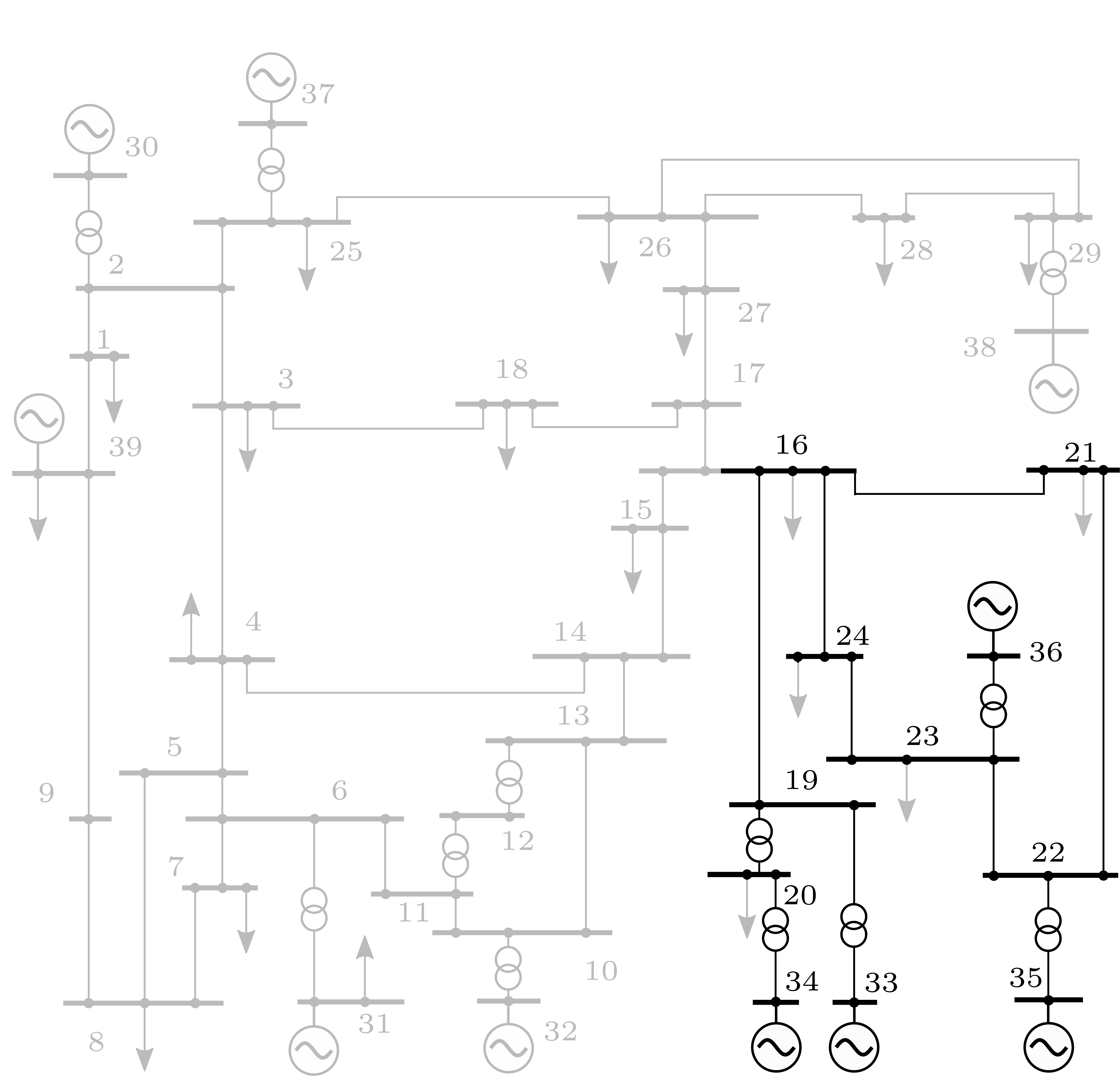
Figure 1: The IEEE 39-bus network.#
ieee39_conv#
A converter-penetrated variant of the same network: five Sauer-Pai synchronous machines, two grid-forming and three grid-following converters, nineteen ZIP loads. Disturbance: a bus fault and its clearing.
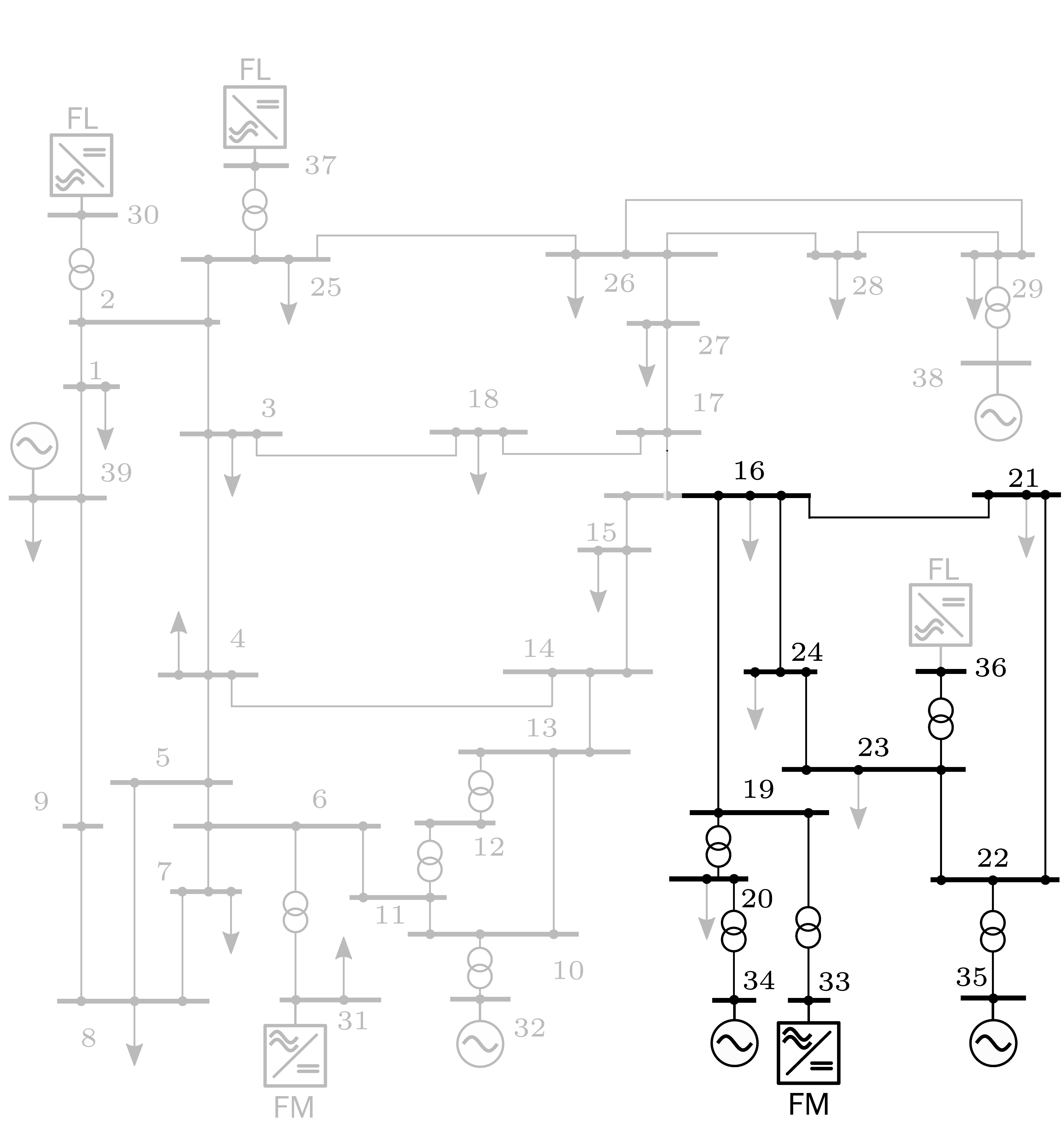
Figure 2: The IEEE 39-bus network with grid-forming and grid-following converters.#
ieee39_ideal#
The 39-bus network with constant-power loads instead of ZIP loads and a longer disturbance sequence: a line fault followed by the line opening, a bus fault and its clearing, and a load step. Inherited from the parent project, where it served as the idealized-measurement scenario, and kept as a functional test that the simulator reproduces the expected response.
ieee39_conv_old#
An earlier converter-penetrated variant, kept for comparison with results produced before the converter models were reworked. Prefer ieee39_conv for new work.
The 14-generator South East Australian system#
A 59-bus, 76-branch, five-area, 50 Hz benchmark with fourteen aggregated power
stations and five static var compensators, from M. Gibbard and D. Vowles,
Simplified 14-Generator Model of the South East Australian Power System,
University of Adelaide, revision 4, 2014. The parameter tables are transcribed
into sea_data.py and sea_dynamics.py; the report itself is not
redistributed.
The case folders are generated by build_sea_system.py and can be validated
against the published load flow and rotor modes with validate_sea.py. Both
are repo-only developer tools (run from a source checkout, not shipped in the
wheel), because they write the case folders next to themselves:
python hermess/systems/sea14gen/build_sea_system.py 1
python hermess/systems/sea14gen/validate_sea.py 1
python hermess/systems/sea14gen/build_sea_system.py 1 --no-pss
sea14gen/case1#
Operating case 1 of the benchmark: twelve round-rotor (GENROU) and two
salient-pole (GENSAL) machines with ST1A and AC1A exciters and speed
stabilizers, five SVCs and thirty-two ZIP loads. Disturbance: a bus fault and its
clearing.
sea14gen/case1_nopss#
Operating case 1 with the power system stabilizers removed, which is how the benchmark exposes its poorly damped inter-area modes.
sea14gen/case1_conv#
Operating case 1 with three of the stations replaced by converters, two grid-forming and one grid-following, keeping the SVCs and the load pattern.
sea14gen/case2 … sea14gen/case6#
The remaining five published operating conditions of the benchmark, spanning
heavy to light system loading, each with the exciter and stabilizer settings of
the report and a _nopss variant with the stabilizers removed. All folders
are generated by the current build_sea_system.py and validated against the
published load flow and rotor modes with validate_sea.py. Disturbance in
every case: a 100 ms bus fault and its clearing.
Case |
Total generation |
Total load |
|---|---|---|
1 |
23030 MW |
22300 MW |
2 |
21590 MW |
21000 MW |
3 |
25430 MW |
24800 MW |
4 |
15050 MW |
14810 MW |
5 |
19060 MW |
18600 MW |
6 |
14840 MW |
14630 MW |
sea14gen/smib#
A single GENROU machine against an infinite bus, used to cross-check the
machine implementation against the benchmark equations in isolation. No
disturbance.