
 HERMESS
Governors#
The turbine-governor strategy is plugged onto a machine with the governor
keyword, for example governor = "TGOV1". It reads the rotor speed and
produces the mechanical power \(p_m\) for the shaft.
|
Class |
Description |
|---|---|---|
|
Pure speed-droop governor: primary frequency response with no turbine lag dynamics, the \(T_{ch}, T_{sv} \to 0\) limit of |
|
|
Constant mechanical power: no turbine or governor dynamics, the zero-response limit of |
|
|
TGOV1 steam turbine-governor: droop-controlled valve and steam-chest lag (P. |
|
|
Type II speed governor: a droop on the frequency deviation through one lead-lag, added to the constant reference power (F. |
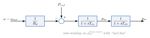
TGOV1: droop, servo and reheater lags (GOVCONST holds \(p_m\)
constant; Droop keeps only the droop).#
- class hermess.devices.governor.GOVCONST[source]
Constant mechanical power: no turbine or governor dynamics, the zero-response limit of
Droop(\(R_d \to \infty\)).Selected on a machine line with
governor = "GOVCONST".Model.
\[0 = -p_m + P_{ref}\]Used by benchmarks that deliberately exclude prime-mover dynamics, such as the 14-generator South East Australian system (Gibbard and Vowles 2014), whose small- and large-signal models have no turbine or governor representation.
Symbols.
Code
Symbol
Meaning
Default
pm\(p_m\)
mechanical power (private algebraic) [p.u.]
Pref\(P_{ref}\)
mechanical-power setpoint (set by the initialization)
- class hermess.devices.governor.Droop[source]
Pure speed-droop governor: primary frequency response with no turbine lag dynamics, the \(T_{ch}, T_{sv} \to 0\) limit of
TGOV1.Selected on a machine line with
governor = "Droop".Model. The mechanical power follows the speed deviation instantaneously and is therefore a device-private algebraic variable (no states):
\[0 = -p_m + P_{ref} - \frac{\omega - \omega_{net}}{R_d}\]with \(\omega\) the absolute per-unit rotor speed and \(\omega_{net} = 1\) p.u., so that \(p_m = P_{ref}\) at steady state.
pmrides the device-private-algebraic mechanism and the swing equation reads it throughSynchronous.var_sym('pm').Symbols.
Code
Symbol
Meaning
Default
Rd\(R_d\)
speed droop constant
0.05
pm\(p_m\)
mechanical power (private algebraic) [p.u.]
Pref\(P_{ref}\)
mechanical-power setpoint (set by the initialization)
- class hermess.devices.governor.TGOV1[source]
TGOV1 steam turbine-governor: droop-controlled valve and steam-chest lag (P. W. Sauer and M. A. Pai, Power System Dynamics and Stability, p. 100). The framework default.
Selected on a machine line with
governor = "TGOV1".Model.
\[\begin{split}T_{sv} \, \dot{p}_{sv} &= -p_{sv} + P_{ref} - \frac{\omega - \omega_{net}}{R_d} \\ T_{ch} \, \dot{p}_m &= p_{sv} - p_m\end{split}\]with \(\omega\) the absolute per-unit rotor speed and \(\omega_{net} = 1\) p.u., so that \(p_{sv} = p_m = P_{ref}\) at steady state. With
incl_limthe valve equation is multiplied by the anti-windup switch that freezes the valve at \(p_{sv}^{max,min}\).Symbols.
Code
Symbol
Meaning
Default
Rd\(R_d\)
speed droop constant
0.05
Tch\(T_{ch}\)
steam chest time constant [s]
0.05
Tsv\(T_{sv}\)
steam valve time constant [s]
1.5
psv_max/psv_min\(p_{sv}^{max,min}\)
valve limits (with
incl_lim)10 / -10
psv\(p_{sv}\)
steam valve position (state) [p.u.]
pm\(p_m\)
mechanical power (state) [p.u.]
Pref\(P_{ref}\)
mechanical-power setpoint (set by the initialization)
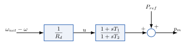
Type II governor: the frequency deviation acts through the droop and one lead-lag, added to the constant reference power.#
- class hermess.devices.governor.TGTypeII[source]
Type II speed governor: a droop on the frequency deviation through one lead-lag, added to the constant reference power (F. Milano, Power System Modelling and Scripting, 2010; the PSID
TGTypeII).Selected on a machine line with
governor = "TGTypeII".Model. The lead-lag is realized as one lag state plus feedthrough, so the mechanical power is a device-private algebraic:
\[\begin{split}u &= \frac{1}{R_d} \left( \omega_{net} - \omega \right) \\ T_2 \, \dot{x}_g &= u - x_g \\ 0 &= -p_m + \frac{T_1}{T_2} \left( u - x_g \right) + x_g + P_{ref}\end{split}\]with \(\omega\) the absolute per-unit rotor speed. At steady state \(x_g = u = 0\) and \(p_m = P_{ref}\). Like the PSID reference (which publishes this output as the mechanical torque without a \(1/\omega\) factor), the output feeds the swing equation unmodified.
Symbols.
Code
Symbol
Meaning
Default
Rd\(R_d\)
speed droop constant
0.05
T1\(T_1\)
lead (transient droop) time constant [s]
1
T2\(T_2\)
lag time constant [s]
2
xg\(x_g\)
lead-lag lag state [p.u.]
pm\(p_m\)
mechanical power (private algebraic) [p.u.]
Pref\(P_{ref}\)
mechanical-power setpoint (set by the initialization)