 HERMESS
Synchronous machines#
A synchronous machine is specified with the electromagnetic model as the machine class, and the various controller strategies are plugged onto it. The electromagnetic model exchanges the air-gap power \(P_e\) and the rotor motion \(\delta, \omega\) with the shaft strategy, reads the field voltage \(E_{fd}\) from the AVR strategy (which sums the stabilizing signal \(V_s\) of the PSS strategy into its voltage error) and the mechanical power \(p_m\) from the governor strategy, and injects its stator current into the network:
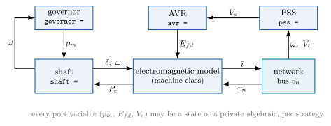
How a machine is composed: the machine class implements the electromagnetic model; shaft, governor, AVR and PSS are pluggable strategies selected by keyword on the machine line.#
The shipped machine classes:
Class |
Description |
|---|---|
Base class of all synchronous machines: composition of an electromagnetic model (the subclass) with pluggable shaft, governor, AVR and PSS strategies, and the network coupling. |
|
Two-axis (transient) synchronous machine (F. |
|
Subtransient (Anderson-Fouad) synchronous machine (F. |
|
Subtransient Sauer-Pai synchronous machine WITH stator (electromagnetic) flux dynamics (P. |
|
Marconato synchronous machine WITH stator flux dynamics: six electromagnetic states, with the subtransient pair kept as EMFs behind the subtransient reactances and an additional field-voltage feedthrough time constant \(T_{AA}\) (F. |
|
Subtransient Sauer-Pai machine with NEGLECTED stator dynamics: the sixth-order model, with the stator as algebraic equations (P. |
|
Subtransient Sauer-Pai 6th-order machine expressed as an explicit DAE. |
|
Subtransient Sauer-Pai machine (with stator dynamics) with the stator currents exposed as explicit device-private algebraic variables. |
|
Sixth-order round-rotor synchronous machine (PSS/E GENROU): two rotor windings per axis, in the K-coefficient form of Gibbard & Vowles 2014, Appendix I.5.1, eqs. (11)-(24). |
|
Fifth-order salient-pole synchronous machine (PSS/E GENSAL): two rotor windings on the d-axis, one on the q-axis. |
Transient (two-axis) model#
A two-axis dynamic approximation of a synchronous generator, following [1].
- class hermess.devices.synchronous.SynchronousTransient(avr=None, governor=None, pss=None, shaft=None)[source]
Two-axis (transient) synchronous machine (F. Milano, Power System Modelling and Scripting, 2010).
Selected in a system file by the class name in the first column:
SynchronousTransient, idx = "SG1", bus = "1", Sn = 300, avr = "SEXST", ...Model. Stator currents from the algebraic stator relation (per machine)
\[\begin{split}\begin{bmatrix} R_s & -x'_q \\ x'_d & R_s \end{bmatrix} \begin{bmatrix} i_d \\ i_q \end{bmatrix} = \begin{bmatrix} e'_d - v_d \\ e'_q - v_q \end{bmatrix},\end{split}\]transient EMF dynamics and air-gap power
\[\begin{split}T'_d \, \dot{e}'_q &= -e'_q + E_{fd} - (x_d - x'_d)\, i_d \\ T'_q \, \dot{e}'_d &= -e'_d + (x_q - x'_q)\, i_q \\ P_e &= e'_d i_d + e'_q i_q + (x'_q - x'_d)\, i_d i_q .\end{split}\]The rotor motion is written by the shaft strategy (default
SingleMass, \(\dot{\delta} = \omega_b(\omega - \omega_{ref})\), \(2H\dot{\omega} = p_m - P_e - D(\omega - \omega_{ref}) - f\omega\) with \(\omega\) the absolute per-unit speed); \(E_{fd}\) comes from the AVR strategy and \(p_m\) from the governor strategy.Symbols (model-specific; base-machine and strategy parameters are documented in
Synchronousand the strategy classes):Code
Symbol
Meaning
Default
x_dprim\(x'_d\)
d-axis transient reactance [p.u.]
0.05
x_qprim\(x'_q\)
q-axis transient reactance [p.u.]
0.1
T_dprim\(T'_d\)
d-axis transient time constant [s]
8
T_qprim\(T'_q\)
q-axis transient time constant [s]
0.8
e_dprim\(e'_d\)
d-axis EMF behind transient reactance (state) [p.u.]
e_qprim\(e'_q\)
q-axis EMF behind transient reactance (state) [p.u.]
Subtransient model#
A subtransient (Anderson-Fouad) approximation, following [1].
- class hermess.devices.synchronous.SynchronousSubtransient(avr=None, governor=None, pss=None, shaft=None)[source]
Subtransient (Anderson-Fouad) synchronous machine (F. Milano, Power System Modelling and Scripting, 2010).
Selected in a system file by the class name in the first column:
SynchronousSubtransient, idx = "SG1", bus = "1", Sn = 300, avr = "IEEEDC1A", ...Model. Stator currents from the algebraic stator relation with the subtransient EMFs,
\[\begin{split}\begin{bmatrix} R_s & -x''_q \\ x''_d & R_s \end{bmatrix} \begin{bmatrix} i_d \\ i_q \end{bmatrix} = \begin{bmatrix} e''_d - v_d \\ e''_q - v_q \end{bmatrix},\end{split}\]transient and subtransient EMF dynamics and air-gap power
\[\begin{split}T'_d \, \dot{e}'_q &= -e'_q + E_{fd} - (x_d - x'_d)\, i_d \\ T'_q \, \dot{e}'_d &= -e'_d + (x_q - x'_q)\, i_q \\ T''_d \, \dot{e}''_q &= e'_q - e''_q - (x'_d - x''_d)\, i_d \\ T''_q \, \dot{e}''_d &= e'_d - e''_d + (x'_q - x''_q)\, i_q \\ P_e &= e''_d i_d + e''_q i_q + (x''_q - x''_d)\, i_d i_q .\end{split}\]Rotor motion, exciter and governor as in
SynchronousTransient(shaft, AVR and governor strategies).Symbols (model-specific):
Code
Symbol
Meaning
Default
x_dprim\(x'_d\)
d-axis transient reactance [p.u.]
0.05
x_qprim\(x'_q\)
q-axis transient reactance [p.u.]
0.1
T_dprim\(T'_d\)
d-axis transient time constant [s]
8
T_qprim\(T'_q\)
q-axis transient time constant [s]
0.8
x_dsec\(x''_d\)
d-axis subtransient reactance [p.u.]
0.01
x_qsec\(x''_q\)
q-axis subtransient reactance [p.u.]
0.01
T_dsec\(T''_d\)
d-axis subtransient time constant [s]
0.001
T_qsec\(T''_q\)
q-axis subtransient time constant [s]
0.001
e_dprim\(e'_d\)
d-axis transient EMF (state) [p.u.]
e_qprim\(e'_q\)
q-axis transient EMF (state) [p.u.]
e_dsec\(e''_d\)
d-axis subtransient EMF (state) [p.u.]
e_qsec\(e''_q\)
q-axis subtransient EMF (state) [p.u.]
Sauer-Pai model, with stator dynamics#
Extends the subtransient model with stator flux dynamics, following [3].
- class hermess.devices.synchronous.SynchronousSubtransientSP(avr=None, governor=None, pss=None, shaft=None)[source]
- Subtransient Sauer-Pai synchronous machine WITH stator (electromagnetic)
flux dynamics (P. W. Sauer and M. A. Pai, Power System Dynamics and Stability, 1998). The stator transients make this the machine to pair with dynamic line models (
line_dyn=True).Selected in a system file by the class name in the first column:
SynchronousSubtransientSP, idx = "SG1", bus = "1", Sn = 300, avr = "SEXST", ...Model. With the coupling coefficients
\[g_{d1} = \frac{x''_d - x_l}{x'_d - x_l}, \quad g_{q1} = \frac{x''_q - x_l}{x'_q - x_l}, \quad g_{d2} = \frac{1 - g_{d1}}{x'_d - x_l}, \quad g_{q2} = \frac{1 - g_{q1}}{x'_q - x_l},\]the stator currents are explicit in the flux states,
\[\begin{split}i_d &= \frac{1}{x''_d} \bigl( -\psi_d + g_{d1} e'_q + (1 - g_{d1}) \psi_{d2} \bigr) \\ i_q &= \frac{1}{x''_q} \bigl( -\psi_q - g_{q1} e'_d + (1 - g_{q1}) \psi_{q2} \bigr),\end{split}\]the rotor-circuit and stator-flux dynamics are
\[\begin{split}T'_d \, \dot{e}'_q &= -e'_q - (x_d - x'_d) \bigl( g_{d1} i_d - g_{d2} \psi_{d2} + g_{d2} e'_q \bigr) + E_{fd} \\ T'_q \, \dot{e}'_d &= -e'_d + (x_q - x'_q) \bigl( g_{q1} i_q - g_{q2} \psi_{q2} - g_{q2} e'_d \bigr) \\ T''_d \, \dot{\psi}_{d2} &= -\psi_{d2} + e'_q - (x'_d - x_l)\, i_d \\ T''_q \, \dot{\psi}_{q2} &= -\psi_{q2} - e'_d - (x'_q - x_l)\, i_q \\ \dot{\psi}_d &= \omega_b \bigl( R_s i_d + \omega \psi_q + v_d \bigr) \\ \dot{\psi}_q &= \omega_b \bigl( R_s i_q - \omega \psi_d + v_q \bigr)\end{split}\]with \(\omega_b = 2\pi f_n\), \(\omega\) the absolute per-unit rotor speed, and air-gap power \(P_e = \psi_d i_q - \psi_q i_d\). Rotor motion, exciter and governor come from the shaft, AVR and governor strategies.
Symbols (model-specific; \(g_{d1}, g_{q1}, g_{d2}, g_{q2}\) are computed from the reactances, not inputs):
Code
Symbol
Meaning
Default
x_l\(x_l\)
leakage reactance [p.u.]
0.1
x_dprim\(x'_d\)
d-axis transient reactance [p.u.]
0.05
x_qprim\(x'_q\)
q-axis transient reactance [p.u.]
0.1
T_dprim\(T'_d\)
d-axis transient time constant [s]
8
T_qprim\(T'_q\)
q-axis transient time constant [s]
0.8
x_dsec\(x''_d\)
d-axis subtransient reactance [p.u.]
0.01
x_qsec\(x''_q\)
q-axis subtransient reactance [p.u.]
0.01
T_dsec\(T''_d\)
d-axis subtransient time constant [s]
0.001
T_qsec\(T''_q\)
q-axis subtransient time constant [s]
0.001
gd1gq1gd2gq2\(g_{d1}, g_{q1}, g_{d2}, g_{q2}\)
coupling coefficients (derived)
e_dprim\(e'_d\)
d-axis transient EMF (state) [p.u.]
e_qprim\(e'_q\)
q-axis transient EMF (state) [p.u.]
psid\(\psi_d\)
d-axis stator flux (state) [p.u.]
psiq\(\psi_q\)
q-axis stator flux (state) [p.u.]
psid2\(\psi_{d2}\)
d-axis subtransient flux (state) [p.u.]
psiq2\(\psi_{q2}\)
q-axis subtransient flux (state) [p.u.]
Sauer-Pai model, without stator dynamics#
The Sauer-Pai formulation with the stator transients neglected, a sixth-order model [3].
- class hermess.devices.synchronous.SynchronousSubtransientSP6(avr=None, governor=None, pss=None, shaft=None)[source]
- Subtransient Sauer-Pai machine with NEGLECTED stator dynamics: the
sixth-order model, with the stator as algebraic equations (P. W. Sauer and M. A. Pai, Power System Dynamics and Stability, 1998).
Selected in a system file by the class name in the first column:
SynchronousSubtransientSP6, idx = "SG1", bus = "1", Sn = 300, ...Model. The rotor-circuit dynamics and the coupling coefficients \(g_{d1}, g_{q1}, g_{d2}, g_{q2}\) are identical to
SynchronousSubtransientSP; the four stator unknowns \((i_d, i_q, \psi_d, \psi_q)\) are instead defined by the algebraic stator block\[\begin{split}0 &= -i_d + \frac{1}{x''_d} \bigl( -\psi_d + g_{d1} e'_q + (1 - g_{d1}) \psi_{d2} \bigr) \\ 0 &= -i_q + \frac{1}{x''_q} \bigl( -\psi_q - g_{q1} e'_d + (1 - g_{q1}) \psi_{q2} \bigr) \\ 0 &= R_s i_d + \omega \psi_q + v_d \\ 0 &= R_s i_q - \omega \psi_d + v_q\end{split}\]which this class eliminates symbolically (a 4x4 linear solve per machine at model-build time); the explicit-DAE variant
SynchronousSubtransientSP6DAEhands the same block to the integrator as private algebraic equations instead. \(\omega\) is the absolute per-unit speed, and the air-gap power is \(P_e = \psi_d i_q - \psi_q i_d\). Rotor motion, exciter and governor come from the shaft, AVR and governor strategies.Symbols (model-specific; \(g_{d1}, g_{q1}, g_{d2}, g_{q2}\) are computed from the reactances, not inputs):
Code
Symbol
Meaning
Default
x_l\(x_l\)
leakage reactance [p.u.]
0.1
x_dprim\(x'_d\)
d-axis transient reactance [p.u.]
0.05
x_qprim\(x'_q\)
q-axis transient reactance [p.u.]
0.1
T_dprim\(T'_d\)
d-axis transient time constant [s]
8
T_qprim\(T'_q\)
q-axis transient time constant [s]
0.8
x_dsec\(x''_d\)
d-axis subtransient reactance [p.u.]
0.01
x_qsec\(x''_q\)
q-axis subtransient reactance [p.u.]
0.01
T_dsec\(T''_d\)
d-axis subtransient time constant [s]
0.001
T_qsec\(T''_q\)
q-axis subtransient time constant [s]
0.001
gd1gq1gd2gq2\(g_{d1}, g_{q1}, g_{d2}, g_{q2}\)
coupling coefficients (derived)
e_dprim\(e'_d\)
d-axis transient EMF (state) [p.u.]
e_qprim\(e'_q\)
q-axis transient EMF (state) [p.u.]
psid2\(\psi_{d2}\)
d-axis subtransient flux (state) [p.u.]
psiq2\(\psi_{q2}\)
q-axis subtransient flux (state) [p.u.]
Explicit-DAE variants#
The same two Sauer-Pai machines with the stator equations kept as algebraic constraints instead of being eliminated. Useful when the stator algebraic variables are needed explicitly, for instance together with dynamic line models.
- class hermess.devices.synchronous.SynchronousSubtransientSP_DAE(avr=None, governor=None, pss=None, shaft=None)[source]
- Subtransient Sauer-Pai machine (with stator dynamics) with the stator
currents exposed as explicit device-private algebraic variables.
Identical physics to
SynchronousSubtransientSP, but the stator currentsi_d, i_qare declared as private algebraic variables (_algebs_int) with their defining equations0 = -i + <expr>handed to the DAE solver, rather than inlined as explicit expressions of the flux states. ReproducesSynchronousSubtransientSPto integrator tolerance.A parity vehicle for the private-algebraic mechanism: the parent model initialises robustly and the defining equations are linear with a trivially non-singular Jacobian (index-1).
Selected in a system file by the class name in the first column:
SynchronousSubtransientSP_DAE, idx = "SG1", bus = "1", ...Symbols. As in
SynchronousSubtransientSP, plus the private algebraicsid_alg(\(i_d\)) andiq_alg(\(i_q\)).
- class hermess.devices.synchronous.SynchronousSubtransientSP6DAE(avr=None, governor=None, pss=None, shaft=None)[source]
Subtransient Sauer-Pai 6th-order machine expressed as an explicit DAE.
Identical physics to
SynchronousSubtransientSP6, but the four stator unknowns (i_d, i_q, psi_d, psi_q) are declared as device-private algebraic variables/equations (_algebs_int) and handed to the DAE solver rather than symbolically eliminated with a per-instanceca.solve. Serves as a parity vehicle for the private-algebraic mechanism: it reproducesSynchronousSubtransientSP6to integrator tolerance.The stator block is linear in the unknowns, so the parent’s
ca.solveis the exact solution ofg = 0; the DAE integrator converges to the same values via a numerical Newton solve per step instead of a closed-form expression built once.Selected in a system file by the class name in the first column:
SynchronousSubtransientSP6DAE, idx = "SG1", bus = "1", ...Symbols. As in
SynchronousSubtransientSP6, plus the private algebraicsid_alg(\(i_d\)),iq_alg(\(i_q\)),psid_alg(\(\psi_d\)) andpsiq_alg(\(\psi_q\)).
PSS/E-style machines#
Round-rotor and salient-pole machines in the PSS/E parameter convention, used by the 14-generator South East Australian benchmark.
- class hermess.devices.synchronous.GENROU(avr=None, governor=None, pss=None, shaft=None)[source]
- Sixth-order round-rotor synchronous machine (PSS/E GENROU): two rotor
windings per axis, in the K-coefficient form of Gibbard & Vowles 2014, Appendix I.5.1, eqs. (11)-(24). A general-purpose machine model (the SEA benchmark is one user). States: \(\delta, \omega, E'_q, \psi_{kd}, E'_d, \psi_{kq}\); the stator is algebraic with the transformer voltages and the speed dependency of the rotational voltages neglected, and magnetic saturation disabled:
\[\begin{split}T'_{d0}\dot{E}'_q &= E_{fd} - [K_{1d}E'_q + K_{2d}\psi_{kd} + K_{3d}I_d] \\ T''_{d0}\dot{\psi}_{kd} &= E'_q - \psi_{kd} - (X'_d - X_a) I_d \\ T'_{q0}\dot{E}'_d &= K_{1q}E'_d + K_{2q}\psi_{kq} + K_{3q}I_q \\ T''_{q0}\dot{\psi}_{kq} &= E'_d - \psi_{kq} + (X'_q - X_a) I_q\end{split}\]with the stator equations \(v_d = -R_s I_d + X''_q I_q + \psi''_q\), \(v_q = -R_s I_q - X''_d I_d + \psi''_d\), the subtransient flux linkages (19)-(20) and the coupling coefficients (22)/(24). The air-gap power follows from the stator equations as \(P_e = \psi''_d I_q + \psi''_q I_d + (X''_q - X''_d) I_d I_q\). The
+(X'_q - X_a) I_qsign in the last differential equation is deliberate (see the sign note inelectromagnetic()): with the stator convention above, the q-axis steady state must reproducev_d = X_q I_q. It is independently cross-validated against the PSID GENROU reference equations. All reactances/time constants in per unit on the machine MVA rating. Rotor motion, exciter and governor come from the shaft, AVR and governor strategies; \(\omega\) is the absolute per-unit speed.Selected in a system file by the class name in the first column:
GENROU, idx = "BPS_2", bus = "201", avr = "AVRST1A", governor = "GOVCONST", pss = "PSSSEA", ...Symbols (model-specific; base-machine and strategy parameters are documented in
Synchronousand the strategy classes):Code
Symbol
Meaning
Default
x_a\(X_a\)
stator leakage reactance [p.u.]
0.15
x_dprim\(X'_d\)
d-axis transient reactance [p.u.]
0.30
x_qprim\(X'_q\)
q-axis transient reactance [p.u.]
0.50
x_dsec\(X''_d\)
d-axis subtransient reactance [p.u.]
0.20
x_qsec\(X''_q\)
q-axis subtransient reactance [p.u.]
0.20
T_d0prim\(T'_{d0}\)
d-axis transient open-circuit time constant [s]
8
T_q0prim\(T'_{q0}\)
q-axis transient open-circuit time constant [s]
1
T_d0sec\(T''_{d0}\)
d-axis subtransient open-circuit time constant [s]
0.04
T_q0sec\(T''_{q0}\)
q-axis subtransient open-circuit time constant [s]
0.10
e_qprim\(E'_q\)
q-axis transient EMF (state) [p.u.]
psi_kd\(\psi_{kd}\)
d-axis damper-winding flux linkage (state) [p.u.]
e_dprim\(E'_d\)
d-axis transient EMF (state) [p.u.]
psi_kq\(\psi_{kq}\)
q-axis damper-winding flux linkage (state) [p.u.]
- class hermess.devices.synchronous.GENSAL(avr=None, governor=None, pss=None, shaft=None)[source]
- Fifth-order salient-pole synchronous machine (PSS/E GENSAL): two rotor
windings on the d-axis, one on the q-axis. The d-axis circuits and the equations of motion are those of
GENROU; the q-axis transient pair \((E'_d, \psi_{kq})\) is replaced by the single subtransient flux state \(\psi''_q\), in the K-coefficient form of Gibbard & Vowles 2014, Appendix I.5.2, eqs. (25)-(26):\[T''_{q0}\,\dot{\psi}''_q = -\psi''_q + (X_q - X''_q) I_q .\]The
+(X_q - X''_q) I_qsign is deliberate (the q-axis steady state must give \(\psi''_q = (X_q - X''_q) I_q\) so thatv_d = X_q I_q); it is cross-validated against the PSID GENSAL reference equations, which define theirpsi_q''state with the opposite sign.Selected in a system file by the class name in the first column:
GENSAL, idx = "HPS_1", bus = "101", avr = "AVRST1A", governor = "GOVCONST", ...Symbols. As in
GENROU, with the q-axis transient pair replaced by:Code
Symbol
Meaning
Default
psi_qsec\(\psi''_q\)
q-axis subtransient flux linkage (state) [p.u.]
Marconato model#
The Milano/Marconato six-state machine with stator flux dynamics, the
counterpart of the PSID MarconatoMachine used by the PSCAD-benchmarked
multi-machine case.
- class hermess.devices.synchronous.Marconato(avr=None, governor=None, pss=None, shaft=None)[source]
- Marconato synchronous machine WITH stator flux dynamics: six
electromagnetic states, with the subtransient pair kept as EMFs behind the subtransient reactances and an additional field-voltage feedthrough time constant \(T_{AA}\) (F. Milano, Power System Modelling and Scripting, 2010, eqs. 15.16-15.18; the PSID
MarconatoMachine).Selected in a system file by the class name in the first column:
Marconato, idx = "SG1", bus = "1", Sn = 100, avr = "AVRSimple", ...Model. With the derived coefficients
\[\gamma_d = \frac{T''_d\, x''_d}{T'_d\, x'_d} \left( x_d - x'_d \right), \qquad \gamma_q = \frac{T''_q\, x''_q}{T'_q\, x'_q} \left( x_q - x'_q \right),\]the stator currents are explicit in the states,
\[i_d = \frac{1}{x''_d} \left( e''_q - \psi_d \right), \qquad i_q = \frac{1}{x''_q} \left( -e''_d - \psi_q \right),\]and the rotor-circuit and stator-flux dynamics are
\[\begin{split}T'_d \, \dot{e}'_q &= -e'_q - (x_d - x'_d - \gamma_d)\, i_d + \left(1 - \frac{T_{AA}}{T'_d}\right) E_{fd} \\ T'_q \, \dot{e}'_d &= -e'_d + (x_q - x'_q - \gamma_q)\, i_q \\ T''_d \, \dot{e}''_q &= -e''_q + e'_q - (x'_d - x''_d + \gamma_d)\, i_d + \frac{T_{AA}}{T'_d} E_{fd} \\ T''_q \, \dot{e}''_d &= -e''_d + e'_d + (x'_q - x''_q + \gamma_q)\, i_q \\ \dot{\psi}_d &= \omega_b \left( R_s i_d + \omega \psi_q + v_d \right) \\ \dot{\psi}_q &= \omega_b \left( R_s i_q - \omega \psi_d + v_q \right)\end{split}\]with \(\omega_b = 2\pi f_n\), \(\omega\) the absolute per-unit rotor speed, and air-gap power \(P_e = \psi_d i_q - \psi_q i_d\). It is cross-validated state for state against the PSID
MarconatoMachine(which derives the same \(\gamma_{d,q}\)). Rotor motion, exciter and governor come from the shaft, AVR and governor strategies.Symbols (model-specific; \(\gamma_d, \gamma_q\) are computed from the parameters, not inputs):
Code
Symbol
Meaning
Default
x_dprim\(x'_d\)
d-axis transient reactance [p.u.]
0.1813
x_qprim\(x'_q\)
q-axis transient reactance [p.u.]
0.25
x_dsec\(x''_d\)
d-axis subtransient reactance [p.u.]
0.14
x_qsec\(x''_q\)
q-axis subtransient reactance [p.u.]
0.18
T_dprim\(T'_d\)
d-axis transient time constant [s]
5.89
T_qprim\(T'_q\)
q-axis transient time constant [s]
0.6
T_dsec\(T''_d\)
d-axis subtransient time constant [s]
0.5
T_qsec\(T''_q\)
q-axis subtransient time constant [s]
0.023
T_aa\(T_{AA}\)
field-voltage feedthrough (additional leakage) time constant [s]
0
e_dprim/e_qprim\(e'_d,\ e'_q\)
transient EMFs (states) [p.u.]
e_dsec/e_qsec\(e''_d,\ e''_q\)
subtransient EMFs (states) [p.u.]
psid/psiq\(\psi_d,\ \psi_q\)
stator fluxes (states) [p.u.]