 HERMESS
Shafts#
The shaft strategy is plugged onto a machine with the shaft keyword, for
example shaft = "Shaft4Mass". It carries the rotor motion
\(\delta, \omega\), exchanging the air-gap power \(P_e\) with the
electromagnetic model and the mechanical power \(p_m\) with the governor.
|
Class |
Description |
|---|---|---|
|
Four-mass torsional shaft: HP – IP – LP – GEN in a linear chain. |
|
|
Five-mass torsional shaft: HP – IP – LP – GEN – EXC in a linear chain. |
|
|
Single rigid rotor mass: the classic swing equation. |
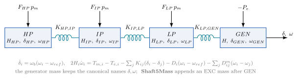
The torsional shaft as a chain of rotor masses coupled by stiffness \(K_{ij}\); the single-mass default keeps only the GEN mass.#
- class hermess.devices.shaft.SingleMass[source]
Single rigid rotor mass: the classic swing equation. The framework default.
Selected on a machine line with
shaft = "SingleMass".Model.
\[\begin{split}\dot{\delta} &= \omega_b \, (\omega - \omega_{ref}) \\ 2 H \, \dot{\omega} &= p_m - P_e - D \, (\omega - \omega_{ref}) - f \, \omega\end{split}\]with \(\omega_b = 2 \pi f_n\) the base angular frequency, \(\omega_{ref}\) the per-machine reference frequency (1 p.u.), \(p_m\) the governor’s mechanical power and \(P_e\) the electromagnetic air-gap power. The shaft reuses the machine’s own inertia \(H\), damping \(D\) and rotor friction \(f\), so it declares no parameters of its own.
Symbols.
Code
Symbol
Meaning
Default
delta\(\delta\)
rotor angle wrt the synchronous frame (state) [rad]
omega\(\omega\)
absolute per-unit rotor speed, 1.0 at synchronism (state) [p.u.]
(machine)
\(H, D, f\)
inertia [s], damping and rotor friction of the host machine
- class hermess.devices.shaft.Shaft4Mass[source]
Four-mass torsional shaft: HP – IP – LP – GEN in a linear chain.
Selected on a machine line with
shaft = "Shaft4Mass".Model. Each mass \(i\) carries an angle and an absolute per-unit speed; adjacent masses are coupled by elastic shaft sections (see
MultiMassShaftfor the general form):\[\begin{split}\dot{\delta}_i &= \omega_b \, (\omega_i - \omega_{ref}) \\ 2 H_i \, \dot{\omega}_i &= T_{m,i} - T_{e,i} - \sum_{j \sim i} K_{ij} (\delta_i - \delta_j) - D_i (\omega_i - \omega_{ref}) - \sum_{j \sim i} D_{m,ij} (\omega_i - \omega_j)\end{split}\]The turbine masses HP, IP and LP receive the fractions \(F_{hp}, F_{ip}, F_{lp}\) of the governor’s mechanical power (\(T_{m,i} = F_i \, p_m\), fractions summing to 1); the generator mass alone carries the air-gap power (\(T_{e,gen} = P_e\)), the machine’s own \(H, D\) and the rotor friction \(f \omega\). The generator mass keeps the canonical state names
delta/omega, so nothing downstream changes with respect toSingleMass.Symbols.
Code
Symbol
Meaning
Default
H_hp/H_ip/H_lp\(H_i\)
turbine mass inertia constants [s]
0.5 / 1 / 4
D_hp/D_ip/D_lp\(D_i\)
turbine mass self damping
0
K_hp_ip/K_ip_lp/K_lp_gen\(K_{ij}\)
shaft section stiffness [p.u. torque/rad]
30 / 40 / 60
Dm_hp_ip/Dm_ip_lp/Dm_lp_gen\(D_{m,ij}\)
shaft section mutual damping
0
F_hp/F_ip/F_lp\(F_i\)
mechanical-power fractions (sum to 1)
0.3 / 0.3 / 0.4
delta/omega\(\delta, \omega\)
generator-mass angle [rad] and absolute speed [p.u.] (states)
delta_hp/omega_hp\(\delta_{hp}, \omega_{hp}\)
HP mass angle and speed (states)
delta_ip/omega_ip\(\delta_{ip}, \omega_{ip}\)
IP mass angle and speed (states)
delta_lp/omega_lp\(\delta_{lp}, \omega_{lp}\)
LP mass angle and speed (states)
- class hermess.devices.shaft.Shaft5Mass[source]
Five-mass torsional shaft: HP – IP – LP – GEN – EXC in a linear chain.
Selected on a machine line with
shaft = "Shaft5Mass".Model. As
Shaft4Mass, with an additional exciter mass EXC on the far side of the generator; for each mass \(i\) of the chain (seeMultiMassShaftfor the general form):\[\begin{split}\dot{\delta}_i &= \omega_b \, (\omega_i - \omega_{ref}) \\ 2 H_i \, \dot{\omega}_i &= T_{m,i} - T_{e,i} - \sum_{j \sim i} K_{ij} (\delta_i - \delta_j) - D_i (\omega_i - \omega_{ref}) - \sum_{j \sim i} D_{m,ij} (\omega_i - \omega_j)\end{split}\]EXC carries no mechanical and no electrical power; it is a passive inertia coupled through the GEN–EXC shaft section, relevant for the higher torsional modes.
Symbols. As
Shaft4Mass, plus:Code
Symbol
Meaning
Default
H_hp/H_ip/H_lp/H_exc\(H_i\)
non-generator mass inertia constants [s]
0.5 / 1 / 4 / 0.1
D_hp/D_ip/D_lp/D_exc\(D_i\)
non-generator mass self damping
0
K_hp_ip/K_ip_lp/K_lp_gen/K_gen_exc\(K_{ij}\)
shaft section stiffness [p.u. torque/rad]
30 / 40 / 60 / 20
Dm_hp_ip/Dm_ip_lp/Dm_lp_gen/Dm_gen_exc\(D_{m,ij}\)
shaft section mutual damping
0
F_hp/F_ip/F_lp\(F_i\)
mechanical-power fractions (sum to 1)
0.3 / 0.3 / 0.4
delta/omega\(\delta, \omega\)
generator-mass angle [rad] and absolute speed [p.u.] (states)
delta_hp/omega_hp\(\delta_{hp}, \omega_{hp}\)
HP mass angle and speed (states)
delta_ip/omega_ip\(\delta_{ip}, \omega_{ip}\)
IP mass angle and speed (states)
delta_lp/omega_lp\(\delta_{lp}, \omega_{lp}\)
LP mass angle and speed (states)
delta_exc/omega_exc\(\delta_{exc}, \omega_{exc}\)
EXC mass angle and speed (states)