
 HERMESS
Automatic voltage regulators#
The AVR strategy is plugged onto a machine with the avr keyword, for
example avr = "SEXST". It reads the terminal voltage and the stabilizing
signal \(V_s\) of the PSS strategy and produces the field voltage
\(E_{fd}\).
|
Class |
Description |
|---|---|---|
|
IEEE Std 421.5 AC1A exciter (small-signal form, no limits or saturation), as used by the 14-generator South East Australian benchmark (Gibbard and Vowles 2014, Fig. 21, Tables 16 and 27). |
|
|
Constant field voltage: no excitation dynamics, the zero-response limit of any exciter (\(K_A \to 0\) with the operating point held). |
|
|
Kundur two-area AVR: transducer plus lead-lag (transient gain reduction), with the field voltage as an algebraic output (Kundur, Power System Stability and Control, 1994, two-area example). |
|
|
|
|
|
|
|
|
All-ODE realization of the Kundur two-area AVR (transducer plus lead-lag with transient gain reduction), with the lead realized through the derivative of the measurement so that \(E_{fd}\) stays a differential state. |
|
|
IEEE Std 421.5 ST1A static exciter (small-signal form, no limits), as used by the 14-generator South East Australian benchmark (Gibbard and Vowles 2014, Fig. 20, Tables 16 and 26). |
|
|
Simple proportional exciter: the field voltage is a pure integrator on the voltage error (the PSID |
|
|
IEEE DC1A rotating exciter with stabilizing rate feedback (P. |
|
|
Simplified static exciter: a single first-order lag on the voltage error. |
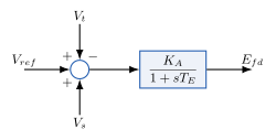
SEXST: first-order static exciter.#
- class hermess.devices.avr.SEXST[source]
Simplified static exciter: a single first-order lag on the voltage error.
Selected on a machine line with
avr = "SEXST".Model.
\[T_E \, \dot{E}_{fd} = -E_{fd} + K_A \left( V_{ref} - V_t + V_s \right)\]with \(V_t = |\bar{v}_n|\) the terminal-voltage magnitude and \(V_s\) the stabilizer signal (0 when no PSS is attached).
Symbols.
Code
Symbol
Meaning
Default
KA\(K_A\)
voltage regulator gain
200
TE\(T_E\)
exciter time constant [s]
0.1
Efd_max/Efd_min\(E_{fd}^{max,min}\)
field-voltage limits (with
incl_lim)5 / 0
Efd\(E_{fd}\)
field voltage (state) [p.u.]
Vf_ref\(V_{ref}\)
voltage setpoint (set by the initialization)
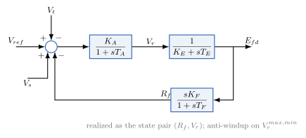
IEEE DC1A: regulator, rotating exciter and stabilizing rate feedback.#
- class hermess.devices.avr.IEEEDC1A[source]
IEEE DC1A rotating exciter with stabilizing rate feedback (P. W. Sauer and M. A. Pai, Power System Dynamics and Stability, p. 100).
Selected on a machine line with
avr = "IEEEDC1A".Model.
\[\begin{split}T_E \, \dot{E}_{fd} &= -K_E \, E_{fd} + V_r \\ T_F \, \dot{R}_f &= -R_f + \frac{K_F}{T_F} E_{fd} \\ T_A \, \dot{V}_r &= -V_r + K_A \Bigl( R_f - \frac{K_F}{T_F} E_{fd} + V_{ref} - V_t + V_s \Bigr)\end{split}\]with \(V_t = |\bar{v}_n|\) and \(V_s\) the stabilizer signal. With
incl_limthe \(V_r\) equation is multiplied by the anti-windup switch that freezes the regulator at \(V_r^{max,min}\).Symbols.
Code
Symbol
Meaning
Default
KA\(K_A\)
voltage regulator gain
200
TA\(T_A\)
voltage regulator time constant [s]
0.015
KF\(K_F\)
rate-feedback (stabilizer) gain
1
TF\(T_F\)
rate-feedback time constant [s]
0.1
KE\(K_E\)
exciter field constant (no saturation)
1
TE\(T_E\)
exciter time constant [s]
0.04
Vr_max/Vr_min\(V_r^{max,min}\)
regulator limits (with
incl_lim)5 / 0
Efd\(E_{fd}\)
field voltage (state) [p.u.]
Rf\(R_f\)
rate-feedback state [p.u.]
Vr\(V_r\)
pilot-exciter (regulator) voltage (state) [p.u.]
Vf_ref\(V_{ref}\)
voltage setpoint (set by the initialization)
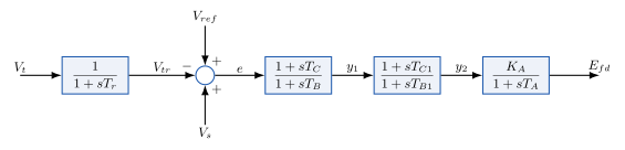
IEEE ST1A: transducer, two lead-lags and the regulator lag.#
- class hermess.devices.avr.AVRST1A[source]
IEEE Std 421.5 ST1A static exciter (small-signal form, no limits), as used by the 14-generator South East Australian benchmark (Gibbard and Vowles 2014, Fig. 20, Tables 16 and 26).
Selected on a machine line with
avr = "AVRST1A".Model. Transducer, two lead-lags (each realized as a lag state plus direct feedthrough), and the regulator lag:
\[\begin{split}T_r \, \dot{V}_{tr} &= V_t - V_{tr}, \qquad e = V_{ref} - V_{tr} + V_s \\ T_B \, \dot{V}_{ll1} &= e - V_{ll1}, \qquad y_1 = \Bigl(1 - \frac{T_C}{T_B}\Bigr) V_{ll1} + \frac{T_C}{T_B}\, e \\ T_{B1} \, \dot{V}_{ll2} &= y_1 - V_{ll2}, \qquad y_2 = \Bigl(1 - \frac{T_{C1}}{T_{B1}}\Bigr) V_{ll2} + \frac{T_{C1}}{T_{B1}}\, y_1 \\ T_A \, \dot{E}_{fd} &= K_A \, y_2 - E_{fd}\end{split}\]with \(V_t = |\bar{v}_n|\) and \(V_s\) the stabilizer signal. \(T_B\) and \(T_{B1}\) must be positive; a unity block is obtained exactly with \(T_C = T_B\), and a transducer given as \(T_r = 0\) in the data is approximated by a small lag (\(10^{-4}\) s, a parasitic pole far above the rotor-mode range).
Symbols.
Code
Symbol
Meaning
Default
KA\(K_A\)
regulator gain
300
TA\(T_A\)
regulator time constant [s]
0.05
Tr\(T_r\)
voltage transducer time constant [s]
1e-4
TB\(T_B\)
first lead-lag denominator time constant [s]
1
TC\(T_C\)
first lead-lag numerator time constant [s]
1
TB1\(T_{B1}\)
second lead-lag denominator time constant [s]
1e-4
TC1\(T_{C1}\)
second lead-lag numerator time constant [s]
1e-4
Vtr\(V_{tr}\)
transducer state [p.u.]
Vll1\(V_{ll1}\)
first lead-lag lag state [p.u.]
Vll2\(V_{ll2}\)
second lead-lag lag state [p.u.]
Efd\(E_{fd}\)
field voltage (state) [p.u.]
Vf_ref\(V_{ref}\)
voltage setpoint (set by the initialization)
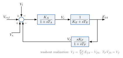
IEEE AC1A: regulator, rotating exciter and washout rate feedback.#
- class hermess.devices.avr.AVRAC1A[source]
IEEE Std 421.5 AC1A exciter (small-signal form, no limits or saturation), as used by the 14-generator South East Australian benchmark (Gibbard and Vowles 2014, Fig. 21, Tables 16 and 27). Exciter saturation, armature reaction and rectifier regulation are neglected (\(K_C = K_D = 0\)), and the lead-lag is unity.
Selected on a machine line with
avr = "AVRAC1A".Model. Washout realization of the rate feedback \(s K_F/(1 + s T_F)\), regulator lag, and rotating exciter:
\[\begin{split}V_f &= \frac{K_F}{T_F} E_{fd} - V_{fb}, \qquad T_F \, \dot{V}_{fb} = V_f \\ T_A \, \dot{V}_r &= K_A \left( V_{ref} - V_t + V_s - V_f \right) - V_r \\ T_E \, \dot{E}_{fd} &= V_r - K_E \, E_{fd}\end{split}\]with \(V_t = |\bar{v}_n|\) (unfiltered; the benchmark data has \(T_r = 0\)) and \(V_s\) the stabilizer signal.
Symbols.
Code
Symbol
Meaning
Default
KA\(K_A\)
regulator gain
400
TA\(T_A\)
regulator time constant [s]
0.02
KE\(K_E\)
exciter constant
1
TE\(T_E\)
exciter time constant [s]
1
KF\(K_F\)
rate feedback gain
0.03
TF\(T_F\)
rate feedback time constant [s]
1
Vr\(V_r\)
regulator output (state) [p.u.]
Efd\(E_{fd}\)
field voltage (state) [p.u.]
Vfb\(V_{fb}\)
rate-feedback filter state [p.u.]
Vf_ref\(V_{ref}\)
voltage setpoint (set by the initialization)
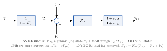
The Kundur two-area AVR family: transducer, gain and transient-gain-reduction lead-lag, in four realizations.#
- class hermess.devices.avr.AVRKundur[source]
Kundur two-area AVR: transducer plus lead-lag (transient gain reduction), with the field voltage as an algebraic output (Kundur, Power System Stability and Control, 1994, two-area example).
Selected on a machine line with
avr = "AVRKundur".Model. The lead-lag \(E_{fd} = K_A \frac{1 + s T_A}{1 + s T_B} (V_{ref} - V_{tr} + V_s)\) is proper but not strictly proper, so its output has a direct feedthrough and is genuinely algebraic. It is realized as one lag-pole state \(V_l\) plus the algebraic output:
\[\begin{split}T_R \, \dot{V}_{tr} &= -V_{tr} + V_t \\ T_B \, \dot{V}_l &= -V_l + K_A \left( V_{ref} - V_{tr} + V_s \right) \\ 0 &= -E_{fd} + \Bigl(1 - \frac{T_A}{T_B}\Bigr) V_l + \frac{T_A}{T_B} K_A \left( V_{ref} - V_{tr} + V_s \right)\end{split}\]with \(V_t = |\bar{v}_n|\) and \(V_s\) the stabilizer signal. The third line is the lead feedthrough \(D = T_A/T_B\).
Efdis exposed viaalgebs()(notstates()) and rides the device-private-algebraic mechanism; the host machine reads it throughSynchronous.var_sym('Efd').Symbols.
Code
Symbol
Meaning
Default
KA\(K_A\)
voltage regulator gain
200
TA\(T_A\)
lead time constant [s]
1
TB\(T_B\)
lag time constant [s]
10
TR\(T_R\)
transducer time constant [s]
0.01
Efd_max/Efd_min\(E_{fd}^{max,min}\)
field-voltage limits (with
incl_lim)5 / 0
Vl\(V_l\)
lag-pole state [p.u.]
Vtr\(V_{tr}\)
transducer state [p.u.]
Efd\(E_{fd}\)
field voltage (private algebraic) [p.u.]
Vf_ref\(V_{ref}\)
voltage setpoint (set by the initialization)
- class hermess.devices.avr.AVRKundur_ODE[source]
All-ODE realization of the Kundur two-area AVR (transducer plus lead-lag with transient gain reduction), with the lead realized through the derivative of the measurement so that \(E_{fd}\) stays a differential state.
Selected on a machine line with
avr = "AVRKundur_ODE".Model.
\[\begin{split}T_R \, \dot{V}_{tr} &= -V_{tr} + V_t \\ T_B \, \dot{E}_{fd} &= -E_{fd} + K_A \left( V_{ref} - V_{tr} + V_s \right) - K_A T_A \, \dot{V}_{tr}\end{split}\]with \(V_t = |\bar{v}_n|\), \(V_s\) the stabilizer signal, and \(\dot{V}_{tr} = (V_t - V_{tr})/T_R\) substituted symbolically. The setpoint-derivative term \(K_A T_A \dot{V}_{ref}\) is omitted; it is zero for a constant setpoint.
Symbols.
Code
Symbol
Meaning
Default
KA\(K_A\)
voltage regulator gain
200
TA\(T_A\)
lead time constant [s]
0.015
TB\(T_B\)
lag time constant [s]
0.02
TR\(T_R\)
transducer time constant [s]
0.01
Efd_max/Efd_min\(E_{fd}^{max,min}\)
field-voltage limits (with
incl_lim)5 / 0
Efd\(E_{fd}\)
field voltage (state) [p.u.]
Vtr\(V_{tr}\)
transducer state [p.u.]
Vf_ref\(V_{ref}\)
voltage setpoint (set by the initialization)
- class hermess.devices.avr.AVRKundur_Filter[source]
AVRKundurwith an additional first-order filter on the exciter output, which removes the algebraic feedthrough (all states differential) and damps unrealistically fast dynamics.Selected on a machine line with
avr = "AVRKundur_Filter".Model.
\[\begin{split}T_R \, \dot{V}_{tr} &= -V_{tr} + V_t \\ T_B \, \dot{V}_l &= -V_l + K_A \, e \\ T_{fd} \, \dot{E}_{fd} &= -E_{fd} + V_l + \frac{T_A}{T_B} \left( K_A \, e - V_l \right)\end{split}\]with the error \(e = V_{ref} - V_{tr} + V_s\), \(V_t = |\bar{v}_n|\), and \(V_s\) the stabilizer signal. The first two lines are the transducer and the lag pole of the lead-lag; the third passes the lead-lag output (lag state plus feedthrough \(T_A/T_B\)) through the output filter \(T_{fd}\).
Symbols.
Code
Symbol
Meaning
Default
KA\(K_A\)
voltage regulator gain
200
TA\(T_A\)
lead time constant [s]
1
TB\(T_B\)
lag time constant [s]
10
TR\(T_R\)
transducer time constant [s]
0.01
Tfd\(T_{fd}\)
exciter output filter time constant [s]
0.01
Efd_max/Efd_min\(E_{fd}^{max,min}\)
field-voltage limits (with
incl_lim)5 / 0
Efd\(E_{fd}\)
field voltage (state) [p.u.]
Vl\(V_l\)
lag-pole state [p.u.]
Vtr\(V_{tr}\)
transducer state [p.u.]
Vf_ref\(V_{ref}\)
voltage setpoint (set by the initialization)
- class hermess.devices.avr.AVRKundur_NoTGR[source]
AVRKundurwith the transient gain reduction removed: a plain high-gain static exciter with only a terminal-voltage transducer.Selected on a machine line with
avr = "AVRKundur_NoTGR".Model.
\[\begin{split}T_R \, \dot{V}_{tr} &= -V_{tr} + V_t \\ 0 &= -E_{fd} + K_A \left( V_{ref} - V_{tr} + V_s \right)\end{split}\]with \(V_t = |\bar{v}_n|\) and \(V_s\) the stabilizer signal. \(E_{fd}\) is an instantaneous gain on the transduced error, hence a private algebraic (read by the machine via
Synchronous.var_sym('Efd')). With a high \(K_A\) and no transient gain reduction this exciter reduces the damping of the electromechanical modes, the classic setting in which a power system stabilizer is needed to restore damping.Symbols.
Code
Symbol
Meaning
Default
KA\(K_A\)
voltage regulator gain
200
TR\(T_R\)
transducer time constant [s]
0.02
Efd_max/Efd_min\(E_{fd}^{max,min}\)
field-voltage limits (with
incl_lim)5 / 0
Vtr\(V_{tr}\)
transducer state [p.u.]
Efd\(E_{fd}\)
field voltage (private algebraic) [p.u.]
Vf_ref\(V_{ref}\)
voltage setpoint (set by the initialization)
Two minimal exciters close the family, useful as limiting cases and for
matching references without excitation dynamics. AVRCONST holds the
field voltage constant at its operating point, and AVRSimple integrates
the voltage error, \(\dot{E}_{fd} = K_v \left( V_{ref} - V_t \right)\).
- class hermess.devices.avr.AVRCONST[source]
Constant field voltage: no excitation dynamics, the zero-response limit of any exciter (\(K_A \to 0\) with the operating point held). The excitation-system counterpart of the constant-power governor
GOVCONST.Selected on a machine line with
avr = "AVRCONST".Model.
\[0 = -E_{fd} + V_{ref}\]\(V_{ref}\) is solved by the initialization to the field voltage that holds the power-flow operating point, and stays frozen afterwards. Used by validation cases that deliberately exclude excitation dynamics, e.g. the cross-tool machine benchmarks against ANDES, whose machines hold \(v_f\) constant when no exciter is attached.
Symbols.
Code
Symbol
Meaning
Default
Efd\(E_{fd}\)
field voltage (private algebraic) [p.u.]
Vf_ref\(V_{ref}\)
field-voltage setpoint (set by the initialization)
- class hermess.devices.avr.AVRSimple[source]
Simple proportional exciter: the field voltage is a pure integrator on the voltage error (the PSID
AVRSimple).Selected on a machine line with
avr = "AVRSimple".Model.
\[\dot{E}_{fd} = K_v \left( V_{ref} - V_t \right)\]with \(V_t = |\bar{v}_n|\) the terminal-voltage magnitude. The integrator makes the steady-state voltage error exactly zero, so the initialization pins \(V_{ref} = V_t\).
Symbols.
Code
Symbol
Meaning
Default
Kv\(K_v\)
integrator gain
1
Efd\(E_{fd}\)
field voltage (state) [p.u.]
Vf_ref\(V_{ref}\)
voltage setpoint (set by the initialization)